
 English
 中文
中文 العربية
 español
Introduction
AI/HPC deployments are forcing a new thermal reality in data centers: racks that used to be “high density” at ~30–50 kW are increasingly planned at 80–120+ kW as GPU-heavy platforms move toward rack-scale designs.
At those densities, air cooling doesn’t fail gracefully. Once airflow and pressure requirements climb beyond what a room can reliably deliver, efficiency drops, noise and fan power rise, and your margin for error shrinks.
Liquid cooling changes the constraint set. By moving most heat into a controlled fluid loop, operators can increase density without betting uptime on perfect airflow, while improving energy and water outcomes depending on how heat is rejected.
This guide maps the practical thresholds, the main architectures, the integration/retrofit controls that keep risk bounded, and a simple way to think about ROI.
Key Takeaway: When rack power moves past “air-manageable,” liquid isn’t just about efficiency—it’s about restoring thermal headroom and operational stability.
Where air hits limits
Density thresholds and fan power cliffs
Air cooling is still the right answer for many rooms—but only up to the point where airflow becomes the dominant engineering problem.
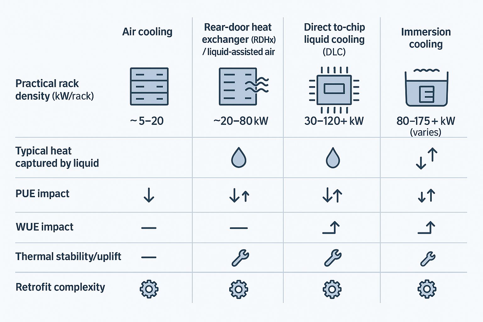
One commonly cited set of thresholds (useful as a planning heuristic, not a universal law) is summarized in Network World’s 2025 discussion of AI density: air is generally adequate up to ~20 kW/rack, RDHx can extend viability toward higher densities, and beyond that direct liquid or immersion becomes the practical path (see “Why AI rack densities make liquid cooling nonnegotiable” (Network World, 2025)).
Why the “cliff” feeling? Fan power doesn’t scale linearly with airflow demand. As racks get hotter, you push for higher CFM and higher static pressure (filters, containment, tighter chassis, denser heatsinks). Fan energy and noise rise quickly, and that extra fan work shows up as more heat you also have to remove.
Practical implication for operators: once you’re redesigning the room around airflow (rather than IT around the room), you’re already paying the penalty.
Thermal stability and throttling risks
GPU-heavy servers are sensitive to transient thermal events: a partially blocked perforated tile, a containment leak, a door left ajar, or a control-loop overshoot can create localized hot air recirculation.
At moderate densities, those issues show up as higher return temps and maybe a comfort-level alert. At very high densities, they show up as performance instability—firmware ramps fans, clocks drop, and the workload takes longer (which can raise total energy for the job).
This is why “more cooling capacity” doesn’t always translate to “more stable compute.” What matters is thermal headroom at the device level and how quickly the system can respond without overshoot.
Space, airflow, and acoustic constraints
High-density air designs are physically bulky:
-
Larger CRAH/CRAC footprints, bigger duct paths, and stricter aisle geometry
-
Tighter control of leakage paths (cable cutouts, gaps, bypass air)
-
Higher acoustic levels as fans ramp and air velocities increase
As you try to densify, you often lose the very space you need to deliver air evenly—especially in retrofits where column grids, existing pipe routes, and legacy containment choices are fixed.
Architectures and KPI gains — liquid cooling for high-density racks
liquid cooling for high-density racks: choosing the right architecture
Key Takeaway: Liquid cooling for high-density racks is an architecture choice, not a single technology—match RDHx, direct-to-chip, or immersion to your density band, service model, and risk tolerance.
Direct-to-chip vs immersion vs RDHx
There isn’t one “liquid cooling.” There are three dominant patterns, each with a different operational shape:
-
RDHx (rear-door heat exchanger): a liquid-to-air coil on the rack exhaust. You keep air-cooled servers, but remove heat at the rack boundary. RDHx is widely positioned as a retrofit bridge; Vertiv describes RDHx supporting higher densities in the ~20–80 kW range depending on design and conditions (see Vertiv’s RDHx retrofit guidance (2025)).
-
Direct-to-chip / direct liquid cooling (DLC): liquid cold plates on CPUs/GPUs move most heat into a secondary coolant loop. Air remains for “residual” components.
-
Immersion: servers (or server boards) are placed in dielectric fluid baths. This can deliver very high density, but the service model and hardware ecosystem change.
In practice, many AI racks are hybrid by design. CUDO’s “AI factory” design notes describe direct-to-chip handling roughly 70–80% of the heat load with air removing the remainder (see CUDO’s “Designing AI factories: Power, cooling & layout” (2025)). That “residual heat” is often why rooms still need disciplined airflow even after adopting liquid.
PUE/WUE impacts at 30–120+ kW
Operators usually care about two questions:
-
Does liquid reduce facility overhead (PUE)?
-
Does it reduce water impact (WUE) or just shift where water is used?
Liquid can improve PUE by reducing fan work, enabling warmer loops (more economization), and focusing mechanical energy where it matters. Network World summarizes reported immersion results in the PUE ~1.02–1.10 (single-phase) and ~1.01–1.03 (two-phase) range in specific deployments (see the cited figures in their 2025 article “Why AI rack densities make liquid cooling nonnegotiable”). Your numbers will depend on climate, heat rejection method (dry coolers vs towers), and how much of the load you actually capture with liquid.
WUE is even more site-dependent. Closed-loop approaches and higher supply temperatures can reduce evaporative dependence, but any design using cooling towers will still have water trade-offs. The point is not that liquid “magically” reduces water—it’s that it gives you more options to design for your local constraints.
liquid cooling for high-density racks: reliability benefits
Reliability improves when you reduce the number of things that must be perfect at the same time.
Liquid cooling for high-density racks shifts critical heat removal from room-level airflow distribution to a controlled loop you can instrument tightly: flow, differential pressure, supply/return temperatures, pump health, and leak status.
That matters because the most common failure modes in high-density air environments are distribution failures—recirculation, bypass, localized blockage, or control instability. With liquid, your thermal margin is less sensitive to small airflow mistakes, and your detection signals are often clearer (a flow drop is harder to ignore than a drifting return-air temperature).
Integration and retrofit
CDUs, loops, and isolation strategy
For most retrofits, the design goal is fault containment:
-
Keep the facility (primary) water system isolated from IT coolant chemistry and cleanliness requirements.
-
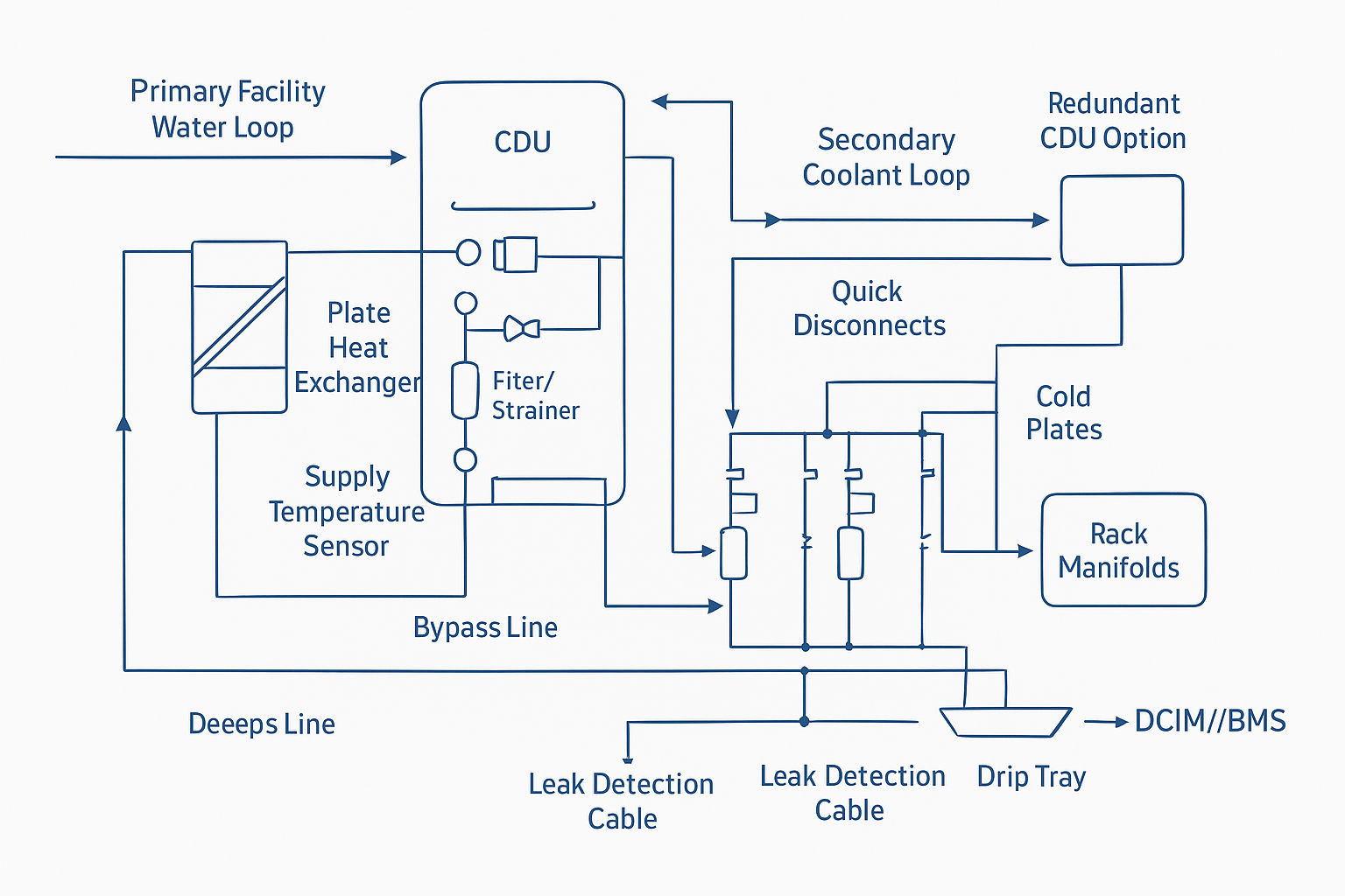
Use a CDU (coolant distribution unit) with a heat exchanger to decouple loops.
-
Design isolation so a single rack, manifold, or row can be taken out of service without draining the room.
A common pattern is:
-
Primary loop (facility side): chilled water or water/glycol to the CDU heat exchanger
-
Secondary loop (IT side): controlled coolant (often treated water/glycol or deionized water depending on OEM requirements) from the CDU to rack manifolds and cold plates
Build in service realities: strainers/filters where they can be accessed, bypass paths to keep flow during maintenance, and N+1 pump strategies where uptime demands it.
Leak detection, QDs, and service SOPs
Leak risk is manageable, but only if you treat it like an engineered safety system—not a hope-and-pray accessory.
Key practices:
-
Quick disconnects (QDs) with verified shutoff behavior, plus drip containment at connection points
-
Leak detection using a mix of point sensors (high-risk joints) and sensing cable (under racks / pipe routes)
-
Defined SOPs for connect/disconnect, filter service, and response escalation (what triggers a local isolation vs a broader shutdown)
-
Commissioning discipline: pressure testing, sensor validation, alarm setpoints, and “tabletop drills” for on-call response
⚠️ Warning: The most dangerous retrofit pattern is “liquid added, but alarm logic not integrated.” A leak sensor that no one monitors is just a false sense of safety.
DCIM/BMS telemetry and controls
At high density, telemetry becomes part of the cooling system. You don’t just monitor temperatures—you manage risk.
Minimum signals most operators standardize:
-
Supply/return temperatures (primary and secondary)
-
Flow and differential pressure per CDU loop
-
Pump status and health (speed, vibration where available)
-
Filter/strainer ΔP (service indicator)
-
Leak alarms (location-aware)
Control principles:
-
Use staged alarms to avoid panic shutdowns (notify → isolate local loop → graceful workload actions → selective EPO only when necessary).
-
Correlate thermal events with workload scheduling when possible (pre-cool, load-following pump control).
Coolnet supports integrated cooling, power, and monitoring—CDUs/heat exchange plus UPS/power distribution and PLC-based telemetry (Modbus options)—which can simplify commissioning and unify alarms across mechanical and electrical systems.
Hybrid deployment patterns
Start with AI/HPC pods
Pods are a risk-control strategy as much as a delivery strategy.
By defining a liquid-ready zone (power, manifolds, CDU capacity, service access, drain/containment plan), you can:
-
Commission once, then replicate
-
Contain failures and maintenance windows
-
Keep the rest of the data hall on proven air patterns
This approach also aligns with procurement realities: long lead times for mechanical and electrical gear are easier to manage when you’re scaling in modular blocks.
Mix liquid chips with optimized air
Hybrid is normal:
-
Liquid captures the highest heat flux components (GPUs/CPUs)
-
Air handles the balance and maintains component-level cooling that isn’t plumbed
What changes is the room: with a large fraction of heat moved to liquid, you can often relax some airflow constraints—but you can’t abandon airflow discipline. The goal is to prevent recirculation and preserve stable intake conditions for the remaining air-cooled components.
Heat reuse opportunities
Warm-water loops and higher return temperatures can make heat reuse more feasible—especially where district heating or nearby process loads exist.
CUDO notes that return temperatures in the 50–60°C range can align with low-temperature district heating networks in the right context (see CUDO’s 2025 piece “Designing AI factories: Power, cooling & layout”). The constraint is governance: heat reuse can reduce operational flexibility, and the economics often depend on local infrastructure and contracts.
ROI and risk framing
Energy, capacity, and floor space levers
The ROI case usually comes from a blend of:
-
Energy: less fan work; more economization hours; more targeted mechanical effort
-
Capacity: more kW per rack and per square foot without rebuilding the room
-
Deferral: delaying a new build by making existing space “AI-ready”
When you frame ROI, treat density as a business lever: the question is often not “Can we cool it?” but “Can we cool it predictably enough to commit capacity and SLAs?”
Uptime assurance and compliance
High-density increases the blast radius of any incident. Risk framing should include:
-
Fault containment (isolation valves, local loop shutdown)
-
Detection coverage (sensing cable + point sensors)
-
Change management (service SOPs, training, drills)
-
Documentation for auditors (commissioning records, alarm tests, maintenance logs)
The goal is to make liquid cooling legible to operations and compliance teams: monitored, testable, and procedurally controlled.
CapEx vs OpEx and lead-time planning
Liquid cooling often shifts spend:
-
Higher upfront integration (CDUs, manifolds, plumbing, monitoring)
-
Lower ongoing penalty from “brute force air” strategies
Lead times matter. If you’re planning AI/HPC growth, the critical path may be power and cooling equipment procurement and commissioning—not the IT hardware.
A practical planning approach is to treat liquid infrastructure as a repeatable module: define a standard pod capacity, keep spares for high-risk components (sensors, QDs), and design for serviceability.
Conclusion
-
Liquid cooling enables reliable 60–120+ kW racks by restoring thermal headroom where air distribution becomes fragile.
-
Expect PUE gains (often discussed on the order of ~0.05–0.15 in well-executed transitions) and, more importantly, stable performance under transient loads.
-
Prioritize isolation, detection, and telemetry so liquid is operationally safe—not just thermally capable.
-
Phase adoption via pods and hybrid approaches to reduce retrofit risk and smooth lead-time constraints.


 IPv6 network supported