
 English
 中文
中文 العربية
 español
Introduction
AI/HPC racks normalizing 120–150kW exceed the practical limits of air cooling—not because operators “haven’t tried hard enough,” but because the airflow and pressure requirements grow faster than the physical space, fan curves, and duct/containment realities can support.
If you’re responsible for uptime and efficiency, you need clear thresholds, retrofit paths, and KPIs for high-density data center cooling—not another vendor pitch. The question isn’t whether liquid cooling works; it’s which liquid or hybrid architecture matches your existing plant, risk posture, and operating model.
Below is a field-aligned map of proven liquid and hybrid options, plus a minimal-downtime migration approach aligned to operator-focused guidance from ASHRAE TC 9.9.
Key takeaways:
-
At 120–150kW/rack, air becomes a distribution/control problem (CFM, pressure drop, hotspots), not just capacity.
-
Hybrid and liquid architectures (RDHx, D2C, immersion) de-risk density when sequenced correctly.
-
Treat CDUs, controls integration, and leak-risk controls as first-class design scope with measurable KPIs (PUE/WUE/uptime).
The 120kW air limit (high-density data center cooling threshold)
Physics and airflow math at 120–150kW
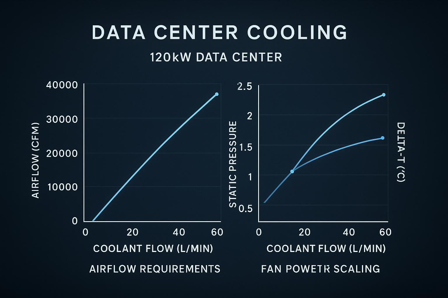
Air cooling is ultimately an energy transport problem: you have to move enough mass flow of air to carry the sensible heat away.
A standard HVAC approximation expresses sensible heat in air as Q = 1.08 × CFM × ΔT(°F) (see Engineering ToolBox’s “Q = 1.08 × CFM × ΔT” equation). Rearranged, CFM = Q / (1.08 × ΔT).
For a rough rack-level sense check:
-
120 kW of IT load is ~409,000 BTU/hr (using 1 kW ≈ 3,412 BTU/hr).
-
If you want a 20°F rise across the rack air path (already aggressive at high density), you’re at roughly 19,000 CFM per rack.
That number is the tell. Even with immaculate containment, the required airflow drives extreme face velocities, high pressure drop through dense server internals, and a level of ducting/return management that doesn’t scale cleanly in real buildings.
Hotspots, throttling, and fan energy
At these densities, “average temperature” stops being a useful control variable. The operational failures are local:
-
Hotspots form faster than your room control loop can react. A few blocked paths (cabling, blanking gaps, partially obstructed filters) can move you from stable operation into localized over-temp.
-
Thermal throttling becomes a capacity problem. When GPUs/accelerators throttle, you don’t just lose performance—you lose predictability for job scheduling and SLA behavior.
-
Fan energy becomes non-trivial. Fan power rises steeply as you chase higher airflow against higher static pressure. Past a point, you’re spending meaningful electrical budget just to move air through increasingly resistive paths—and that electrical input becomes additional heat you must remove.
Key Takeaway: At 120–150kW/rack, air cooling fails first as a control and distribution problem (hotspots, pressure drop, fan power), not as a nameplate cooling-capacity problem.
Why air-assist stalls beyond ~70kW
Hybrid “air-assist” approaches can extend the runway—especially if you remove a large fraction of heat with liquid while leaving residual components to air. But beyond roughly ~70kW/rack, two constraints tend to dominate:
-
Residual heat is still too large for air to handle gracefully. If 20–30% of a 120kW rack remains air-cooled, that’s still 24–36kW of air heat in a single cabinet—already a high-density rack by traditional standards.
-
The last meters are the hardest meters. Even if the room can supply cold air, the rack has to distribute it uniformly across tightly packed nodes without unacceptable pressure drop and acoustic/power penalties.
Liquid options 120–200kW
In high-density data center cooling, the practical question is how much heat you remove with liquid (and where), and how much you leave to room air.
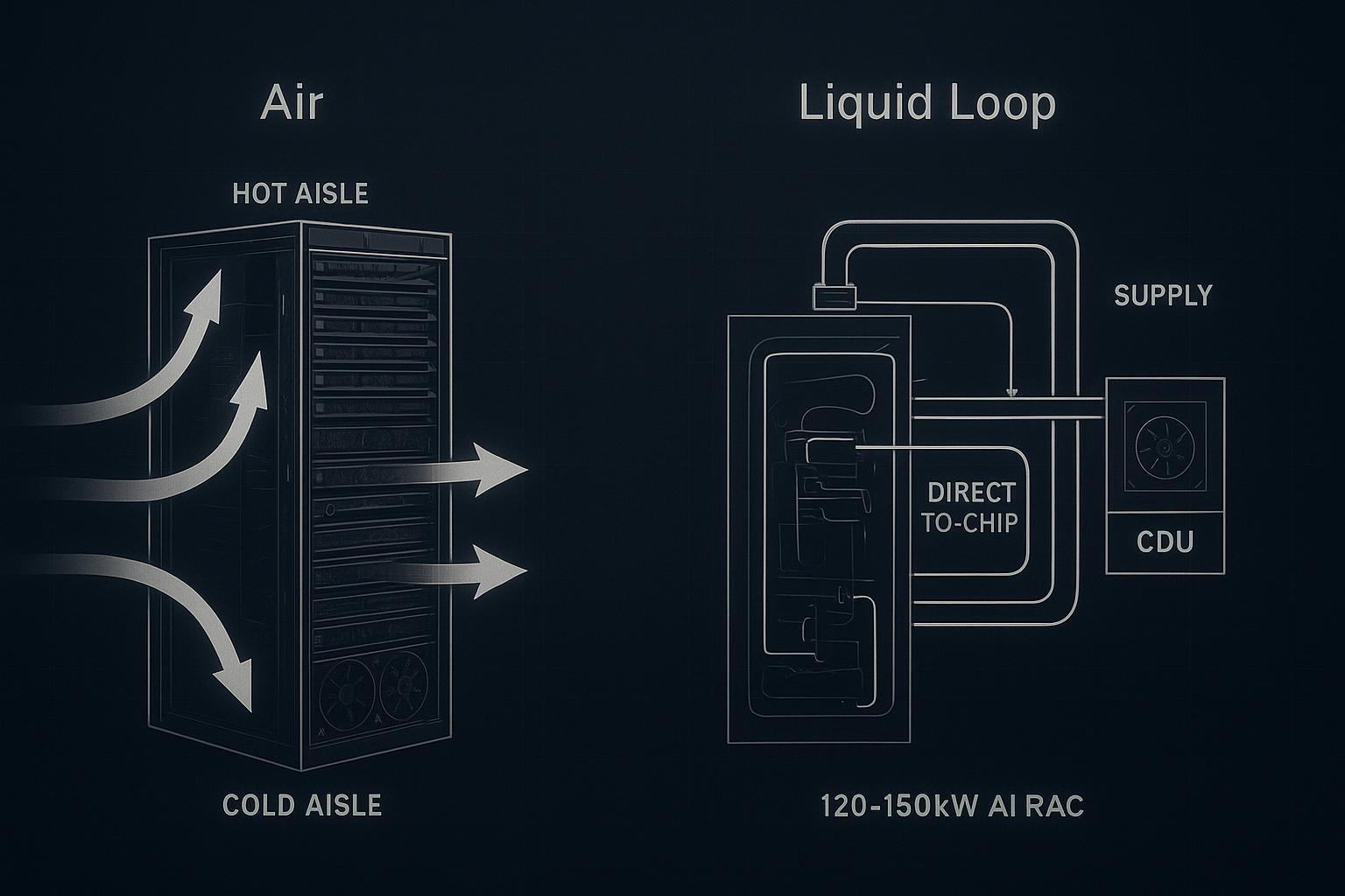
Direct-to-chip cold plates
Direct-to-chip (D2C) uses cold plates on CPUs/GPUs (and sometimes HBM/VRMs), pulling heat into a liquid loop where the heat capacity and thermal conductivity are far higher than air. In practice, this is direct-to-chip liquid cooling: removing the highest heat-flux sources at the point of generation so the rest of the rack is easier to manage.
Operational trade-offs to plan for:
-
CDU and loop architecture: You need a clear boundary between facility heat rejection and the IT-side coolant loop (fluid quality, filtration, pressure control).
-
Condensation management: As supply temperatures move, you must stay above the space dew point (or control dew point aggressively) to avoid condensation risk on wetted components.
-
Commissioning burden: Flow verification, balancing, and alarm validation become first-class tasks.
For operators who want to keep standard rack form factors while enabling very high accelerator power, D2C is often the “default” high-density path.
Active rear-door heat exchangers
Active rear-door heat exchangers (RDHx) capture heat at the rack exhaust, using an air-to-liquid heat exchanger integrated into (or mounted at) the rear door. This can be an effective bridge technology because it preserves a familiar air path inside the server, while moving a large portion of the heat to water.
Where RDHx fits best:
-
Brownfield upgrades where you need fast density uplift without ripping out the entire white space.
-
Mixed loads where some racks remain air-cooled but you want to contain and remove concentrated hot exhaust.
Key limitations:
-
RDHx performance depends on exhaust temperature and airflow uniformity; it doesn’t eliminate airflow distribution problems inside the rack.
-
You still need a robust facility-side interface (water class, redundancy, leak detection, and maintenance access).
Immersion for AI clusters
Immersion cooling (single-phase or two-phase) removes the rack air problem entirely by placing IT hardware in a dielectric fluid. For AI clusters, the appeal is density and consistency: thermal performance becomes less sensitive to front-to-back airflow and room-level mixing.
Trade-offs to consider before you commit:
-
Hardware ecosystem and service model: maintenance procedures, spares strategy, and technician training change.
-
Fluid handling: compatibility, filtration, sampling, and containment become operational disciplines.
-
Integration: heat rejection, monitoring, and safety interlocks must tie cleanly into your site standards.
Immersion tends to work best when deployed as a clearly bounded “pod” or cluster area with well-defined operating procedures.
Retrofit paths, minimal downtime
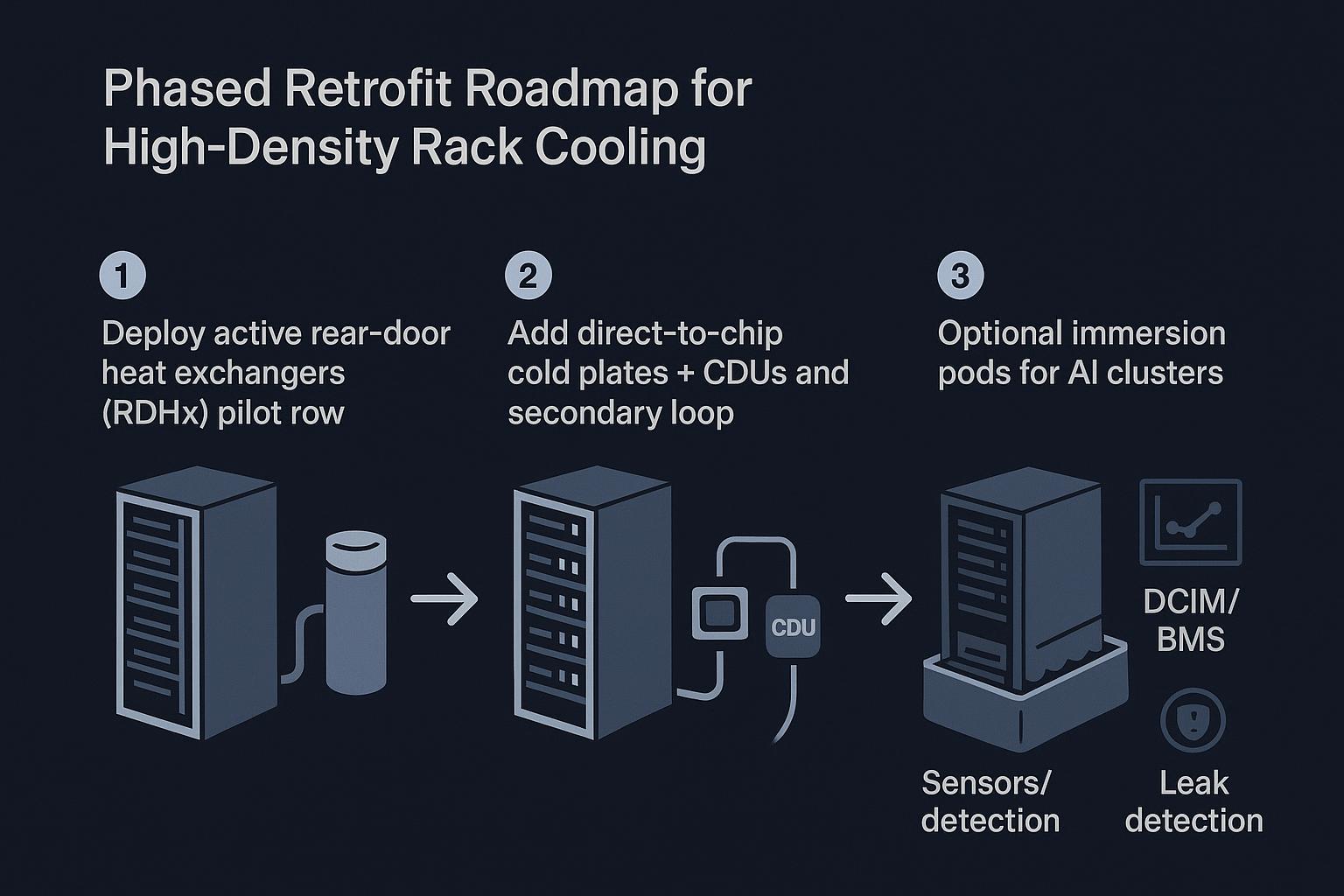
Phased adoption roadmap
A low-disruption path usually starts by moving heat out of the room without changing the whole IT stack, then incrementally shifting the highest heat sources to direct liquid.
A practical sequencing pattern:
-
Start with rack-level heat capture where it reduces risk fastest (often a rear-door heat exchanger (RDHx) for targeted rows).
-
Introduce D2C + CDUs for the racks that drive the thermal bottleneck (AI/HPC rows).
-
Add immersion pods only where the operational model is ready (procedures, spares, training, and containment).
In brownfield sites, an “integrated liquid cooling + CDU” deployment can also be staged as a contained upgrade: for example, Coolnet has implemented integrated liquid-ready building blocks where CDUs regulate IT-side flow/pressure while the facility loop remains stable during phased rack conversions.
Facility interfaces and CDUs
The facility interface is where high-density projects succeed or fail. A coolant distribution unit (CDU) is not just a pump box—it defines the control and protection boundary between what facilities owns and what the IT loop requires.
At a minimum, align on:
-
Loop separation and water quality: treat facility water and IT coolant requirements as different classes unless your IT OEM and chemistry program explicitly allow otherwise.
-
Temperature strategy: choose supply/return targets that avoid condensation risk and fit your heat rejection (dry coolers, chillers, hybrid).
-
Controls and alarms: temperature, differential pressure, flow, conductivity/leak sensing, and pump status should be visible to your operations stack.
For a neutral functional definition, see Coolnet’s overview of what a CDU does.
Risk controls and leak detection
Liquid doesn’t have to increase operational risk—but it does change the failure modes. Design and retrofit plans should treat risk controls as requirements, not add-ons:
-
Leak detection at the right granularity (rack/row), with clear alarm routing and automated shutdown logic where appropriate.
-
Redundancy for flow (pump redundancy, UPS-backed critical controls) so a single failure doesn’t cascade into rapid over-temp.
-
Isolation and serviceability: valves, dripless quick connects where used, and maintainable filter/strainer access.
-
Commissioning discipline: pressure testing, flushing, water chemistry verification, and alarm/failsafe validation.
ASHRAE TC9.9’s guidance on water-cooled servers and liquid cooling emphasizes the importance of correct component selection, processes, and operational controls (see the ASHRAE TC9.9 “Water-Cooled Servers” white paper).
Integration, KPIs, compliance
Controls and DCIM/BMS integration
High-density cooling upgrades should be treated as control systems integration projects, not just mechanical installs.
What to integrate (minimum viable set):
-
CDU telemetry: supply/return temperatures, flow, ΔP, pump state, and alarms.
-
Rack/row sensors: inlet air where residual air remains, plus dew point/humidity where condensation risk exists.
-
Interlocks: what happens on pump failure, leak alarm, or out-of-range dew point.
Done well, this reduces mean time to detect/diagnose and helps you prove KPI outcomes.
KPIs: PUE, WUE, uptime
Operators usually need a KPI set that matches both engineering reality and executive reporting:
-
PUE impact: liquid can reduce fan power and enable higher supply temperatures (depending on architecture), but the real win is often capacity per square foot and reduced hotspot-driven waste.
-
WUE impact: your heat rejection strategy (air-side economization, water-side economization, evaporative assist) matters as much as the in-rack method.
-
Uptime and stability: track thermal excursions, throttle events (if you can instrument them), and cooling alarm rates pre/post retrofit.
Pro Tip: Treat “thermal throttling incidents per week” as an operational KPI alongside PUE/WUE when you’re pushing >70kW/rack.
Standards: ASHRAE and OCP
Standards don’t design your cooling system, but they give you a defensible vocabulary for requirements and audits.
-
ASHRAE: TC9.9 white papers document liquid cooling architectures, components, and operational considerations. For broader adoption context, see ASHRAE TC9.9’s liquid cooling expansion white paper.
-
OCP (Open Compute Project): For operators building multi-vendor AI infrastructure, OCP’s emphasis is interoperability—connectors, manifolds, and CDU integration patterns that reduce lock-in and make liquid deployments repeatable.
Conclusion
Air cooling can be stretched with containment and airflow optimization, but at 120–150kW/rack you hit an engineering wall: airflow volume, pressure drop, hotspots, and fan energy stop scaling.
Liquid and hybrid approaches move you into a controllable regime:
-
Use RDHx to capture exhaust heat quickly with minimal disruption.
-
Use direct-to-chip to remove the dominant heat sources (GPUs/CPUs) and stabilize operation.
-
Use immersion where cluster-level density and a dedicated service model make sense.
Next steps that typically de-risk the project:
-
Classify your facility water and define dew point/condensation guardrails.
-
Size CDUs for required flow/ΔP, redundancy, and alarm integration.
-
Plan the integration work (DCIM/BMS points, interlocks, commissioning) alongside mechanical scope.
-
Set KPI expectations up front (PUE, WUE, uptime/thermal excursions) so the retrofit is measurable—not just installed.


 IPv6 network supported